

|
|
|
|
|
|||||||
| Home | Forums | Gallery | Webcams | Blogs | YouTube Channel | Classifieds | Calendar | Register | FAQ | Donate | Members List | Today's Posts | Search |
 |
|
|
Thread Tools | Display Modes |
 05-10-2007, 05:04 AM
|
#1 |
|
Senior Member

Join Date: Apr 2006
Location: Central MA-Gilford
Posts: 1,411
Thanks: 308
Thanked 117 Times in 94 Posts
|
I was replacing a fuse in boat, which is in an "In-Line" fuse holder. When separating the fuse holder, the fuse crumbled and broke, leaving one end (the metal cap end), in one section of the fuse holder.
The problem is, how do I extract this piece from fuse holder? Cant get any tool into end of holder? Needle-nose pliers do not work? Do not want to damage fuse holder if possible. Any suggestions, short of cutting out fuse holder, and splicing in a new one? Thanks! |

|

|
|
05-12-2007, 07:40 AM
|
#2 |
|
Senior Member

Join Date: Jan 2005
Location: Nashua,Meredith
Posts: 951
Thanks: 213
Thanked 106 Times in 81 Posts
|
get a new fuse holder,you'll need a soldering iron and shrink tube for the best longest lasting repair.cut out the old one trim back the otside of all of the wires about half to 5/8" ,slide shrink tube on and butt ends together over lapping both.solder together,when solder cools slide shrink wrap over connect and use a heat gun or a lighter to shrink wrappers.you can use butt connectors but they don't last long and corrode quickly
|
|
|
|
|
05-12-2007, 08:51 AM
|
#3 | |
|
Senior Member

Join Date: Jan 2005
Location: Florida (Sebring & Keys), Wolfeboro
Posts: 5,788
Thanks: 2,085
Thanked 742 Times in 532 Posts
|
Quote:
 Your problem may be greater than just the fuse holder: if the fuse expired due to too much heat, it may have "soldered itself" into the fuse holder. While a soldering gun will release the "bad end" of the fuse, the wires attached to the fuse holder itself may be compromised. If copper, check that the holder wires are still a bright copper color (not black). If not, soldering in a new fuse holder is a good investment for encounters with future overloads. Also check on the #1 reason for the overload: a new fuse holderor bigger fuseisn't likely the answer.
__________________
Every MP who enters Winter Harbor will pass by my porch of 67 years... 
|
|
|
|
|
|
05-13-2007, 06:35 AM
|
#4 | |
|
Deceased Member

Join Date: Nov 2002
Location: 1/2 way between Boston & Providence
Posts: 573
Blog Entries: 3
Thanks: 32
Thanked 55 Times in 22 Posts
|
Quote:
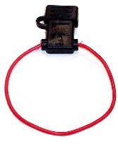
The easiest is to try to push it out using it's own wire. Try pushing the wire of the cap holding end in to the fuse holder. The wire with it's soldered or crimped metal contact may be coaxed out of the fuse holder with the fuse cap sliding out with it. If the wire and holder are too tight to push easily due to rubber gasket or strain relief then try using a little water soluble lubricant on the wire. Should that method not work then here is another suggestion depending on what you have around. Try a stick and something sticky. A stick with fast drying glue on the tip may work. You may already picture how this would work. A Q-tip type stick, small diameter dowel, lolly-pop stick (or whatever) needs to be smaller than than the size of the fuse cap of course. Put the glue on the end of the stick, carefully put the stick in to the fuse holder so that it can get to and adhere to the fuse cap. Once dry, pull it out. Also check for a spring between the contact and the holder. There is a chance that the fuse cap is "welded" to the metal contact inside the holder. You may still be able to get that cap out using the push the wire out method. Then separate the cap from the contact. If that works be sure the contact is clean and smooth before you reuse it as it will allow proper current flow. If the holder, wire or end contacts are corroded or in bad shape you should consider replacing the fuse holder. I've used both methods with success on various in-line and chassis mount holders. Never tried it on a fully integrated plastic coated wire and holder. Let us know how you make out even if you resort to splicing in a new fuse holder (of the right current handling size  ). ).Here are a few sample styles of in-line fuse holders. Two waterproof and one not waterproof. Good luck
__________________
 Amateur HAM Radio What is it? You'll be surprised. When all else fails Ham Radio still works. Shriners Hospitals providing specialized care for children regardless of ability to pay. Find out more or refer a patient. |
|
|
|
|
|
05-13-2007, 10:03 PM
|
#5 |
|
Senior Member

Join Date: Apr 2007
Location: Maynard, MA & Paugus Bay
Posts: 2,522
Thanks: 747
Thanked 344 Times in 257 Posts
|
this has worked for me in the past depending on type, take a strong magnet and hold the fuse holer upside down, put the magnet underneath it an touch them together, it might get pulled out, a magnet that works really well is those retreval magnets they sell in the catalogs for boats, the big ones
or use a paper clip and pry it out, some cheap ideas not to elaborate and both have worked, it depends on the application |
|
|
|
| Sponsored Links |
|
|
|
05-17-2007, 05:55 AM
|
#6 | |
|
Senior Member

Join Date: Jun 2006
Posts: 59
Thanks: 7
Thanked 0 Times in 0 Posts
|
Quote:
|
|
|
|
|
|
05-17-2007, 06:52 PM
|
#7 |
|
Senior Member

Join Date: Apr 2004
Location: Concord NH
Posts: 239
Thanks: 19
Thanked 3 Times in 2 Posts
|
Change the holder and when you do, use a blade type fuse holder and not worry about this ever happening again.
__________________
"He who dies with the most toys wins" 
|
|
|
|
|
05-18-2007, 08:49 AM
|
#8 |
|
Senior Member
Join Date: Apr 2006
Location: Central MA-Gilford
Posts: 1,411
Thanks: 308
Thanked 117 Times in 94 Posts
|
Thanks to everyone for all the suggestions, much appreciated !
The Fuse Holder is "trashed" and must be replaced ! I do have a few questions/responses as follows: Skipper of Sea Que Correct, good guess ! The fuse cap is was indeed "welded" to the metal contact inside the holder. RobMAc You suggested soldering the fuse wires together, then using shrink-wrap to cover solder joint. Great idea ! Using a "lighter" to shrink the plastic cover, not a good idea, as fuse is located near gas tank and gas fumes are prevalent. Can you say "KABOOM" ! Do you have something against using "Butt Connectors" for repair? This was my "plan of attack". Aquadeziac: You suggested using a "Blade Type" fuse holder ? Not familiar with this type? Can you describe, and are they "water-proof" ? You also stated, that if used, I probably wouldn't ever have to replace? Are they that good ? Thanks again folks, you recommendations have been invaluable ! |
|
|
|
|
05-19-2007, 10:00 AM
|
#9 |
|
Senior Member

Join Date: Jul 2004
Posts: 2,974
Thanks: 246
Thanked 736 Times in 438 Posts
|
There are waterproof blade type fues holders available. I think it's great advice to use a blade fuse, wish I'd thought of it.
 Holder 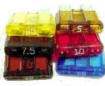 Blade fuses Crimp-style butt connectors are perfectly acceptable. Get the best available at a marine store and seal them. |
|
|
|
|
05-19-2007, 06:00 PM
|
#10 | |
|
Deceased Member
Join Date: Nov 2002
Location: 1/2 way between Boston & Providence
Posts: 573
Blog Entries: 3
Thanks: 32
Thanked 55 Times in 22 Posts
|
My earlier post was written before I saw APS's post. He makes very good points as does Dave R. The fuse is a protective device so you should know what caused it to vaporize or find out why before replacing the fuse and/or holder. I was just answering your original question about removing a stuck fuse cap.
Heat shrink tubing may be shrunk (correct word?) with a hair dryer. Most people do not have the heat gun often used by techies on that stuff. However, the heat shrink tubing may not be waterproof. Water may be able to migrate up the tube. You might want to use a true wire weather sealing product (Radio Shack Coax Seal may be right). You must think about the vibration, wire stress, electric current, temperatures and other conditions that this fuse will likely endure in your boat. You may want to consider having a pro do the work with their marine grade parts, tools and experience. Crimp on connectors can be very good but the crimp tool is important. A poor crimp can be a source of heat and eventually maybe sparks. Err on the side of safety. Good luck Bigdog. Let us know what caused the original fuse to explode or disintergrate. High current spike, small gap between contact and fuse or ...? Quote:
") Let me briefly respond to your statement. In-line fuse holders are sold with specifications including a maximum current handling rating. Often referenced to 30 Volts DC. The replacement in-line fuse comes with a WIRE (see pictures above). That wire MUST be of the appropriate size/rating to handle the maximum current intended and then some. They are sold together as one unit so I stand by my statement. You need to buy an in-line fuse holder that will handle the current. If you want to talk high voltage then the electrical characteristics of the material of the fuse holder can be important. Hope this helps clarify the issue. If you question it others might have too  Happy, safe and moderate speed boating to all
__________________
Amateur HAM Radio What is it? You'll be surprised. When all else fails Ham Radio still works. Shriners Hospitals providing specialized care for children regardless of ability to pay. Find out more or refer a patient. |
|
|
|
|
|
05-20-2007, 10:05 AM
|
#11 |
|
Senior Member
Join Date: Jan 2005
Location: Nashua,Meredith
Posts: 951
Thanks: 213
Thanked 106 Times in 81 Posts
|
as with the previous comment I agree,crimp connectors aren't the best solution in this case.Vibration and movement can cause it to come loose and cause a worse situation.Good luck,look forward to reading what caused the original failure
|
|
|
|
|
05-20-2007, 11:09 AM
|
#12 | |
|
Senior Member

Join Date: May 2007
Posts: 248
Thanks: 6
Thanked 5 Times in 5 Posts
|
Quote:
|
|
|
|
|
|
05-20-2007, 12:31 PM
|
#13 |
|
Senior Member
Join Date: Jul 2004
Posts: 2,974
Thanks: 246
Thanked 736 Times in 438 Posts
|
I almost always solder and heat shrink, but there is absolutely nothing wrong with a properly crimped connection. Every electrical wire/connector connection in your engine compartment is crimped. It's a proven technology.
|
|
|
|
|
05-20-2007, 09:41 PM
|
#14 |
|
Senior Member
Join Date: Apr 2006
Location: Central MA-Gilford
Posts: 1,411
Thanks: 308
Thanked 117 Times in 94 Posts
|
Cut out the old fuse holder and replaced with the "waterproof" type
which holds the fuse in a rubber bootie. Soldered all connections. When I tested the Trim & Trailer switches, the following occurrer: 1. Trailer switch now operating correctly and raises Drive in the UP position. 2. Trim Down, works fine, Solenoid kicked in, and drive went DOWN ! 3. Trim Up, still does not work, solenoid does not "click". Being a very "logical thinking" person, I have to come to the following conclusion why the "UP Trim" switch doesn't work: A. There is a problem with the "UP Solenoid" connections or the Solenoid itself is bad or B. The TRIM Limit switch is bad. Either the contacts in the switch itself or the wiring leading to the switch. or C. The TRIM switch at the shift/throttle lever is bad. Does this make sense ? I'm trying to keep this in a simple perspective, but maybe it isn't ? At least now, I can operate the Drive Up & Down, but using the Trailer switch to get in UP position. You have all given me much helpful info.and is greatly appreciated. Thanks again ! |
|
|
|
|
05-21-2007, 05:27 AM
|
#15 | |
|
Senior Member
Join Date: Jan 2005
Location: Florida (Sebring & Keys), Wolfeboro
Posts: 5,788
Thanks: 2,085
Thanked 742 Times in 532 Posts
|
Quote:
(While agreeing with your implied assessment of solder and heat shrink).
__________________
Every MP who enters Winter Harbor will pass by my porch of 67 years...
|
|
|
|
|
|
05-21-2007, 09:30 AM
|
#16 | |
|
Senior Member

Join Date: Sep 2003
Posts: 1,943
Thanks: 23
Thanked 111 Times in 51 Posts
|
Quote:
__________________
Mee'n'Mac "Never attribute to malice that which can be explained by simple stupidity or ignorance. The latter are a lot more common than the former." - RAH |
|
|
|
|
|
05-21-2007, 09:45 AM
|
#17 | |
|
Senior Member
Join Date: Sep 2003
Posts: 1,943
Thanks: 23
Thanked 111 Times in 51 Posts
|
Quote:
Gee I better write the NASA and let them know.  Actually a proper crimp is every bit as good as a proper solder job. Both can be botched though it's easier to botch the solder job than the crimp which is why crimps are prefered in a marine environment by you average backyard "technician". The basic problem is the excessive solder will wick up the wire and cause it to be stiff. Vibration will work to cause the wire to fail just past this wicking point. A proper crimp doesn't suffer from this malady but may fail if too little pressure (and some times if too much) pressure is used. In either case you need the shrink wrap to keep the moisture out and the wire needs mechanical support to reduce mechanical flexing. Actually a proper crimp is every bit as good as a proper solder job. Both can be botched though it's easier to botch the solder job than the crimp which is why crimps are prefered in a marine environment by you average backyard "technician". The basic problem is the excessive solder will wick up the wire and cause it to be stiff. Vibration will work to cause the wire to fail just past this wicking point. A proper crimp doesn't suffer from this malady but may fail if too little pressure (and some times if too much) pressure is used. In either case you need the shrink wrap to keep the moisture out and the wire needs mechanical support to reduce mechanical flexing.
__________________
Mee'n'Mac "Never attribute to malice that which can be explained by simple stupidity or ignorance. The latter are a lot more common than the former." - RAH |
|
|
|
|
|
05-21-2007, 12:05 PM
|
#18 | |
|
Senior Member
Join Date: Jul 2004
Posts: 2,974
Thanks: 246
Thanked 736 Times in 438 Posts
|
Quote:
|
|
|
|
|
|
05-22-2007, 02:42 AM
|
#19 | |
|
Senior Member
Join Date: Jan 2005
Location: Florida (Sebring & Keys), Wolfeboro
Posts: 5,788
Thanks: 2,085
Thanked 742 Times in 532 Posts
|
Quote:
 IMHO, the very finest connections I've seen were on hand-made vehicles from the 50swith soldered wire ends secured with tiny brass screws. With volume production (and the dreaded production engineer), they went to crimped connections. Botched solder connections (in both 6V and 12V), are a specialty of mine , but I make up for it with strain relief, cable ties, and shrink tubing  . .BTW: Select replacement crimp connectors carefully: some have an aluminum interior and not the proper tinned-copper interior.
__________________
Every MP who enters Winter Harbor will pass by my porch of 67 years...
|
|
|
|
|
|
05-22-2007, 09:06 PM
|
#20 |
|
Senior Member

Join Date: Jul 2002
Location: North Kingstown RI
Posts: 688
Thanks: 143
Thanked 83 Times in 55 Posts
|
When I worked in Marine electronics the only type of lug we used were Burndy lugs with the proper crimp tool, then soldered properly and wrapped in black tape. They are nothing like the ones from the automotive stores. Done properly they would stand up in any salt water environment. Sometimes, in the bilge, we would add shrink wrap over the tape as a backup. My boss (the owner) had a wide reputation for quality installations on pleasure and commercial boats.
__________________
Gene ~ aka "another RI Swamp Yankee" |
|
|
|
|
| Bookmarks |
|
|


 Linear Mode

